Design optimization of chilled water system of Hualong No. 1 electric plant
By Zhaoo Xiao*, Sun Lonfei, Wei Chuancheng, Liu Zhansheng and Zhang Fengge
[Abstract]: Presents the design function of the chilled water (WEC) system of Hualong No. electric plant. Analyses from the two aspects of start-stop switching between water-cooled and air-cooled units, and protection against external disasters Proposes an optimization scheme for manual switching to automatic switching between water-cooled and air-cooled units, and the addition of high-position electric isolation valves, improving the automation level of the WEC system at a small cost and the protection against external disasters.
[Keywords]: electric plant, chilled water system. start-stop switching, external disaster protection. isolation valve
*China Nuclear Power Engineering Co Ltd. Beijing. China
0 introduction
As the third generation nuclear power reactor independently developed by China, Hualong No.1 reactor has greatly improved its safety index compared with the second generation. In order to ensure the stable and safe operation of nuclear power plants, a series of special safety systems and auxiliary support systems are installed to ensure that the special safety systems can perform their safety functions. Among them, the heat trap is one of the key factors for whether the special safety system can perform its safety function after an accident. The heat trap system includes not only the heat trap system that directly derives the decay heat of the reactor, but also the heat trap system that provides necessary environmental conditions for the safety system equipment operation and electrical instrument control equipment (electrical cabinet, instrument control cabinet, etc.), which involves ventilation system, cold water system and equipment cooling water system.
There are five cold water systems in Hualong No.1 nuclear island, which are electrical workshop cold water (WEC), safety workshop cold water (WSC), nuclear island cold water (WNC), personnel passage workshop cold water (WAC) and nuclear waste workshop cold water (WWC).
WEC system is the only nuclear-grade cold water system on the nuclear island, which provides cold water for the safety-grade ventilation system and the middle and low pressure safety injection pump motor to ensure their stable and safe operation, and is one of the important nuclear island auxiliary systems.
1.WEC system functions
The cold water loop of WEC system is a closed loop, and its function is to transfer the heat recovered from the cooling of the ventilation and air conditioning system cooling coils and the motor of the middle and low pressure safety injection pump in the electrical building, safety building, fuel building and auxiliary building to the equipment cooling water (WCC) system or outdoor atmosphere through the chiller to ensure the normal operation of the main control room, distributed control system (DCS) equipment and the middle and low pressure safety injection pump of the nuclear power plant and the habitability of the operators in the main control room. The cold water supply/return water temperature of WEC system adopts the national standard recommended temperature of 7℃/12℃; The water supply temperature of cooling water in WCC system is 10~ 45℃。 Fig. 1 is a flow diagram of WEC system.

WEC system is equipped with two water-cooled chillers and corresponding cold water pumps, one modular air cooled chiller and corresponding cold water pumps. In addition, a cold water storage tank is set up to provide continuous cold water for end users when the chiller is switched. Under normal working conditions, the water-cooled series of train a or train b operates, while the water-cooled series of the other train is set aside. The air-cooled unit is in hot standby state. Under the condition of losing the final heat sink, the water-cooled unit fails, and the running water-cooled series cold pumps continue to run at this time. During the period before the start of the air-cooled unit, cold water is supplied to the end users through the cold water storage tank until the start of the air-cooled unit series is completed.
2.Start-stop switching between water-cooled units and air-cooled units in 2.WEC system
In the original design of WEC system, manual isolation valves were set before and after water cooling units, air cooling units and cold water pumps. The isolation valves before and after the operation train are normally open, and the isolation valves of the standby train and the air-cooled train are normally closed. The switch before running column and standby column is manual switch. When switching between columns, it is necessary to manually switch the corresponding isolation valves locally. Manual switching takes a certain time, during which the cold water storage tank in the system provides continuous cold source for end users. In order to improve the automation level of WEC system, the original scheme is optimized and improved as follows:
1)Change the isolation valves before and after each standby cold water pump and chiller from normally closed state to normally open state. Relying on water pump outlet Check valves are used to isolate the running train from the standby train, and cold water pumps are interlocked with the chillers in the corresponding train, so that a cold water train can be interlocked with the chillers.
2)In order to realize automatic start-stop switching between water-cooled train and air-cooled train equipment in the main control room, "comprehensive fault shutdown of water chillers" is considered Feedback signal: as long as the water-cooled units in the running train fail to stop, the failure stop signal will be sent to the main control room, and the air-cooled units will be started in chain to ensure continuous cooling in the first time. After the air-cooled unit is started, an instruction is sent from the master control room to send on-site operation and maintenance personnel to check the reasons for the failure and shutdown of the water-cooled unit, and the air-cooled unit can be switched to the standby water-cooled train for operation as appropriate.

The optimized process is shown in Figure 2. This optimization and improvement scheme improves the automation control level of WEC system, and realizes the automatic switching between water-cooled and air-cooled units in WEC system. After the water-cooled units fail to stop, the air-cooled units start automatically, ensuring the continuous supply of cold water at the first time, thus maintaining the habitability of personnel in the main control room, the suitable environmental temperature of equipment such as nuclear-level electrical cabinets and DCS cabinets, ensuring the reliable operation of terminal safety-level users, and further ensuring the safety and reliability of power station operation.
3.External disaster protection
The air-cooled units of WEC system are arranged on the roof of the workshop, and the influence of external disasters such as tornadoes and flying objects should be considered. In the original design, if the outdoor air-cooled units or pipes are broken due to flying objects, resulting in excessive water loss of the system, and two rows of safety-level water-cooled units are shut down due to insufficient flow, the outdoor pipe network will be isolated manually, and the demineralized water replenishing valve will be opened to replenish water. This operation takes several hours. Due to the thermal inertia of the end ventilation users, the temperature of each room will not overheat during the cold water loss. In order to better cope with external disasters, more favorable measures need to be taken.

Fig. 3 is a flow diagram of WEC system after adding high-level electric isolation valve, and the scheme adopts the following optimization and improvement measures:
1)set electric isolation valves before and after the air-cooled units, which are interlocked with the system low-pressure alarm. when the system pressure is low (whether it is leakage in other parts of WEC system or break of air-cooled units and outdoor pipes), close the electric isolation valves and cut off the air-cooled unit circuit; When it is detected that the air-cooled unit is running, the interlocking signal will be shielded.
2)Change the hydrating isolation valve from manual to electric, and interlock with low-pressure alarm. When the system pressure is low, the interlock water supply electric valve will be activated Open, automatic filling water.
After taking the above two improvement measures, the problem of system water loss caused by external disasters can be dealt with at the first time, thus ensuring the normal operation of safety-grade water-cooled units.
4.Conclusion
The manual valves before and after the water chillers and pumps in WEC system are changed from normally closed to normally open, the water chillers start and stop the cold water pumps in chain, and the air-cooled units are automatically started in chain by the "comprehensive fault shutdown of water chillers" signal, which realizes the automatic switching between water-cooled units and air-cooled units, reduces the capacity demand for cold water storage tanks, and significantly improves the automation level of the system and the reliability of nuclear-grade cold sources with minor changes.
By adding an electric isolation valve before and after the air-cooled units and interlocking with the system low-voltage alarm, the manual water supply was changed to electric water supply, which solved the common-mode failure problem of two rows of safe units in WEC system caused by tornadoes and flying objects, and enhanced the external disaster protection capability of the system. By optimizing and improving the cold water system of Hualong No.1 Electric Plant, we realize once again that we need to constantly think and summarize the system design of the new reactor type, and constantly put forward better design schemes to make the system design more perfect.
Source: Journal of HV&AC Heating Ventilating & Air Conditioning


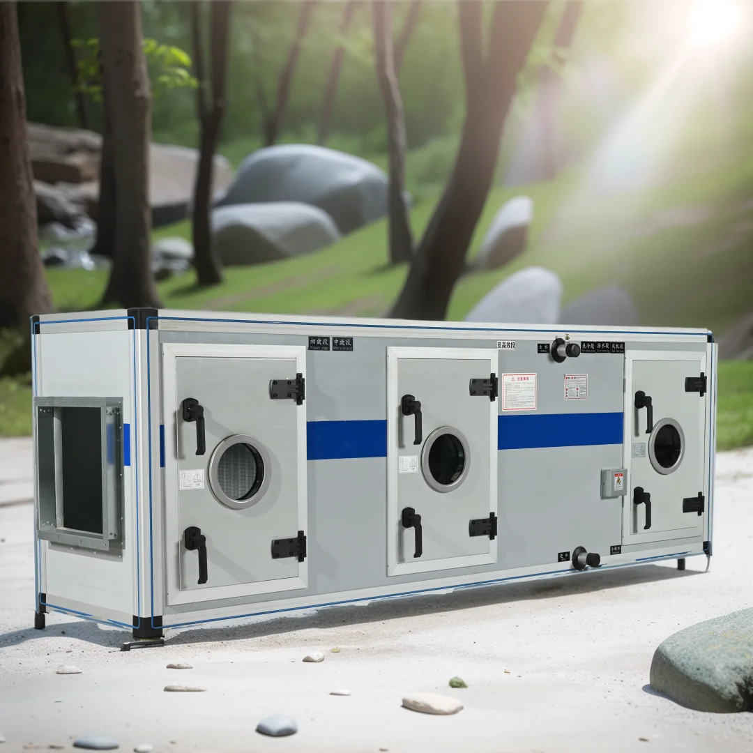 Water source rooftop chiller unit part in HAVC
 The quietness and efficiency of Guqin series Horizontal Ultra-Thin Concealed fan coil units
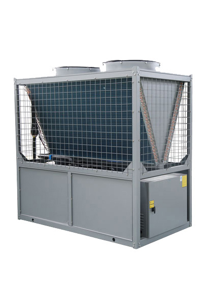 Ultra-low temperature air source heat pump principle and core technology
 Fan Coil Unit Selection And Product Advantages