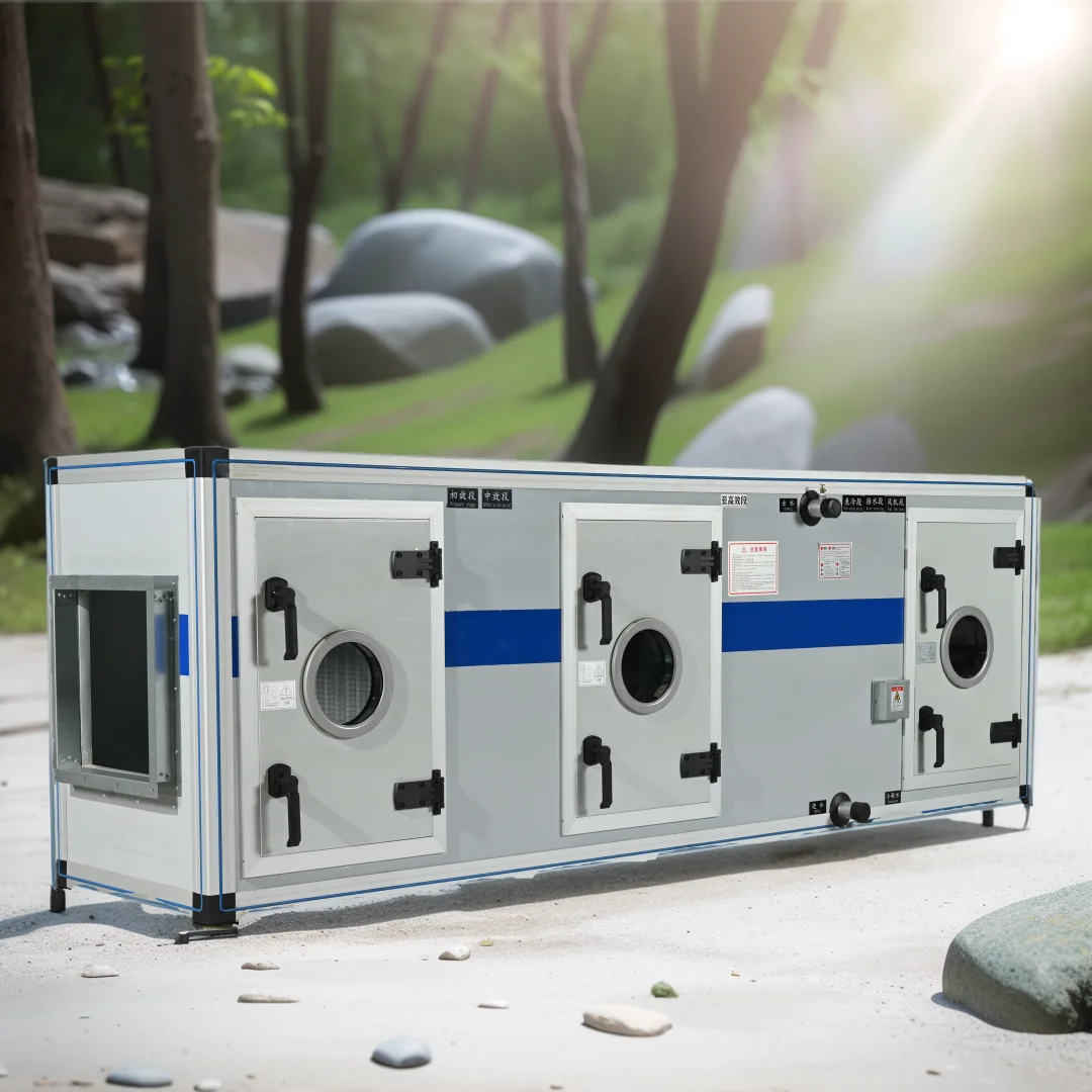
 Water source rooftop chiller unit part in HAVC
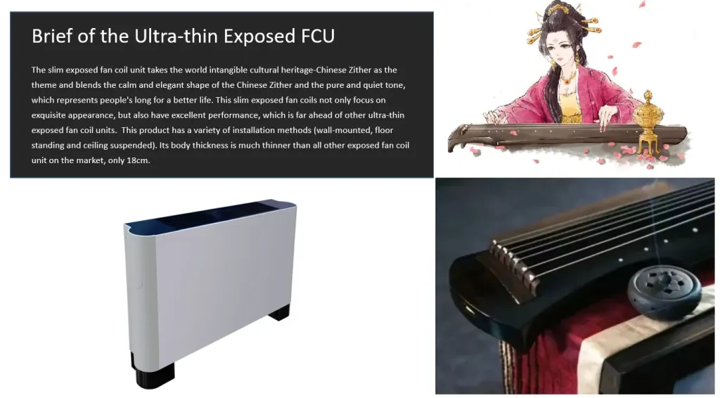 The quietness and efficiency of Guqin series Horizontal Ultra-Thin Concealed fan coil units
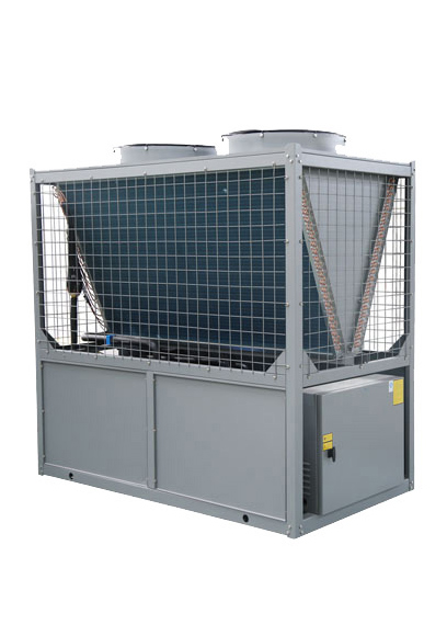 Ultra-low temperature air source heat pump principle and core technology
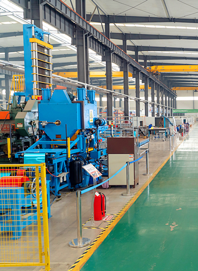 Fan Coil Unit Selection And Product Advantages